PIC serial communication tutorial
Introduction to Serial communication with PIC16F877 microcontroller
CLICK here for a quick PIC serial communication tutorial
In this tutorial we will study the communication component USART (Universal Synchronous Asynchronous Receiver Transmitter) located within the PIC. It is a universal communication component (Synchronous/Asynchronous), which can be used as transmitter or as receiver. We will look at:
- serial and parallel communications
- synchronous and asynchronous communications
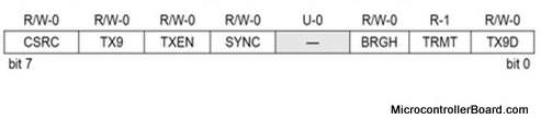
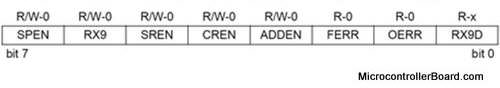
- how to enable serial communication - TXSTA and RCSTA registers
- An example of 8-bit transmission
- An example of 9-bit transmission
- how to calculate the value being placed in the SPBRG register
- USART Transmit and Receive block diagrams
- Max323 Driver/Receiver
- the implementation of the PIC serial communication (C program and a video)
We will show how to set USART in order to allow communication between PIC to PIC or between PIC to a personal computer. We will start with the definition of media concepts. There are two options to differentiate when speaking about transmission of information on the transmission lines:
In order to understand what serial communication is, and emphasize the difference between serial communication and parallel communication, lets take a look at the following example:
We have a multi-bit word, and we want to transmit it from one computer to the second computer.
Using the serial communication:
When using the serial communication we transmit the multi-bit word bit after bit (when at any given moment only one bit will pass).
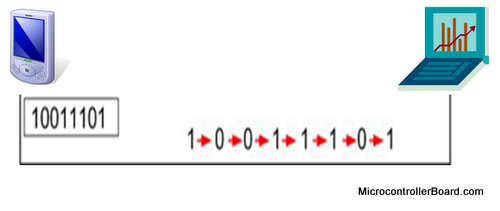
Transmitting the word 10011101 using serial communication.
Using the parallel communication:
When using the parallel communication, however, the number of bits will be transmitted at once from one computer to the second computer.
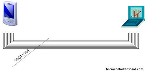
Transmitting the word 10011101 using parallel communication.
In addition to the serial and parallel communications, there are 2 types of communication we will explore:
Synchronous communication
When using the synchronous communication the information is transmitted from the transmitter to the receiver:
- in sequence
- bit after bit
- with fixed baud rate
- and the clock frequency is transmitted along with the bits
That means that the transmitter and the receiver are synchronized between them by the same clock frequency. The clock frequency can be transmitted along with the information, while it is encoded in the information itself, or in many cases there is an additional wire for the clock.
This type of communication is faster compare to the asynchronous communication since it is "constantly transmitting the information, with no stops.
Asynchronous communication
When using the asynchronous communication - the transmitter and the receiver refraining to transmit long sequences of bits because there isn't a full synchronization between the transmitter, that sends the data, and the receiver, that receives the data.
In this case, the information is divided into frames, in the size of byte. Each one of the frame has:
- Start bit marks the beginning of a new frame.
- Stop bit marks the end of the frame.
Frames of information must not necessarily be transmitted at equal time space, since they are independent of the clock.
Enabling Serial Communication
To communicate with external components such as computers or microcontrollers, the PIC micro uses a component called USART - Universal Synchronous Asynchronous Receiver Transmitter. This component can be configured as:
- a Full-Duplex asynchronous system that can communicate with peripheral devices, such as CRT terminals and personal computers
- a Half-Duplex synchronous system that can communicate with peripheral devices, such as A/D or D/A integrated circuits, serial EEPROMs, etc.
To enable the serial communication with PIC micro we must set different parameters within two registers: (click the links for the explanation of each bit)
An example of 8-bit transmission:
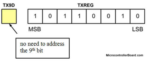
Lets assume that we need to transmit the following information: 10110010. This information will be stored inside TXREG register, which acts as a temporary buffer storage of information prior to transmission.
The bit TX9 will be zero (TX9=0) - which determines that the transmission will be 8-bit transmission, so there is no need to address TX9D bit, which stores the ninth bit of information.
The information before the transmission looks like this:
Transmitting 8 bit data
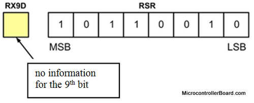
Now, lets define the receiver side to receive 8 bit information. To do so, the register RX9 will be zero (RX9=0). The received information will be stored in the RSR register, which acts as a temporary buffer storage.
The received information will look like this:
Receiving 8 bit data
An example of 9-bit transmission:
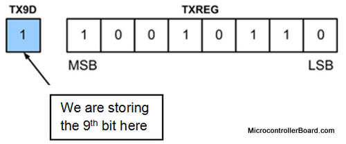
Suppose we want to transmit the following information: 110010110. This information is in the size of 9-bit, so there is not enough space to store all the information in the TXREG register . Thus, we will store the low 8-bit in the register TXREG and the MSB in the TX9D bit.
We will set the TX9 = 1 - enabling transmission of 9-bit data. It is important to note, that first we need to store the 9th bit and only later other 8-bits. This is important because the information of 8 bits may be transmitted immediately once being inside the TXREG register. As a result the transmitted information will be incorrect.
The information before the transmission will look like this:
Transmitting 9 bit data
Now, lets define the receiver side to receive 9 bit information. To do so, the register RX9 will be set (RX9=1). The received, lower 8-bit information, will be stored in the RSR register, which acts as a temporary buffer storage. The higher bit information (MSB) will be stored in RX9D.
The received information will look like this:
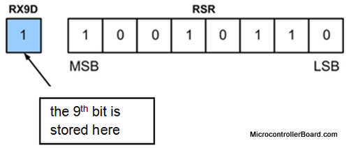
Receiving 9 bit data
Now lets continue the explanation. Each transmission is transmitted in the particular rate (BAUD). The baud rate is measured in units of bps (bit per second) or kbps (kilo bit per second ).
Calculating the value being placed in the SPBRG register
Lets assume we want to transmit using the BAUD rate of 1200bps. This is done by setting the system clock to the value needed. To do so, we need to write a hexadecimal number to the SPBRG register. The value written to the SPBRG register set the clock cycle to the value we want for the BAUD rate.
The size of SPBRG register is 8-bit. As discussed previously, in asynchronous mode, the baud rate of transmission of the information can be set to high speed or to low speed. The rate selection, as already seen, is made by the BRGH bit in TXSTA register:
- 1 = High speed
- 0 = Low speed
SPBRG = (Fosc / (16 x Baud rate)) - 1, BRGH = 1 High Speed
SPBRG = (Fosc / (64 x Baud rate)) - 1, BRGH = 0 Low Speed
The following outlines how the value which is placed in the SPBRG register is being computed, in the case of a high baud rate and low baud rate.
For example:
We want to calculate the hex value that will be placed the register SPBRG, to get the baud rate of 1.2kbps with low speed. The formula SPBRG = (Fosc / (64 x Baud rate)) - 1
was chosen since, its describing the calculation needed for transmission in Low Speed:
SPBRG = (4MHz / (64x1200)) -1 = 51.08
Because it is not possible to write a number with a decimal point to the register, we take only the whole part of the number and place inside the register SPBRG = 51.
The following tables are the BAUD RATES FOR ASYNCHRONOUS MODE BRGH=0 and BRGH=1.
BRGH=0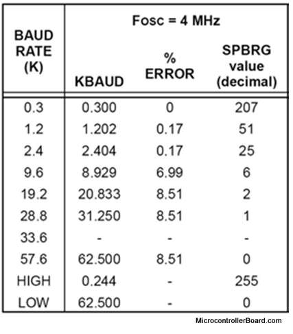 | BRGH=1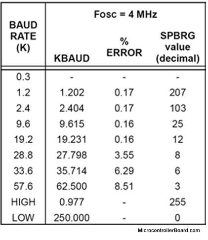 |
USART transmit block diagram
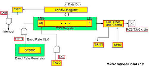
USART transmit block diagram
The information we want to transmit is loaded into the 8-bit register - TXREG. If you want to transmit a 9-bit data, the 9th bit is loaded into TX9D. At the same time, the information above is being loaded into the register TSR, which is used as a temporary buffer before that information is transmitted.
Of course, using 2 registers allows faster the transmission of the data. Once the TXREG register transfers the data to the TSR register, the TXREG register is empty and flag bit, TXIF is set.
As mentioned earlier:
- the register SPBRG sets the baud rate in the desired transmission
- TXIE allows interrupts when TXREG is empty and TXIF is set
- TXEN - Enabling SPBRG
USART receive block diagram
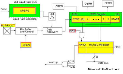
USART receive block diagram
The information is received in the register RSR. If there is a 9-bit transmission, the 9th bit goes into RX9D. After receiving the data in the register RSR, the information is loaded at the same time into the register RCREG. Obviously, using 2 registers allows faster receiving of the data. While the information that was received being transferred into RCREG, the new information has already been received into the register RSR. Of course, the CREN bit needs to be set.
According to the USART TRANSMIT / RECEIVE BLOCK DIAGRAM, that the information that was transmitted via pin RC6 in Port C, is received through the pin RC7 in Port C
Level converter - Max323 Driver/Receiver
For transmitting/receiving the information we use - USART. However, the USART is good for transmitting the information from PIC to PIC, and not enough to transmit from PIC to computer.
Therefore, in order to transmit to a computer we have to add another component, which will allow the transmission in the RS232 protocol and convert between the levels of voltage of the USART to the RS232. The USART logical signal levels are from 0 to 5 volt. However, in the case of RS232 we will need to different levels of voltage.
RS232 uses voltages below (-5V)to represent a logical level "1", and voltages above (5V)to represent a logical level "0". Therefore, to use this protocol we need voltage level conversion. This is possible using the device such as the MAX232. MAX232 is simple component, which operates on 5V.
CLICK here for a detailed explanation about the RS232 protocol.
MAX323 block diagram
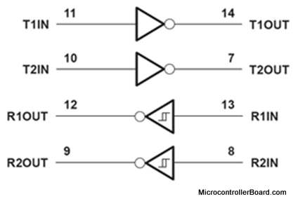
MAX323 block diagram
Basic form of connections
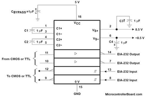
Basic connections
Explanation of the connections:
The output of the USART (information transmitted to the computer) connects to pin 10 or 11. Levels of information are converting to voltage values that are suitable for RS232 and outputs from pins 7 or 14. From here the information advances to the computer.
The information that is transmitted from the computer connects to the pin 8 or 13 of the device. Here again there is conversion levels, but the opposite way, which will apply to USART. Converted signals are outputs through pin 9 or 12.
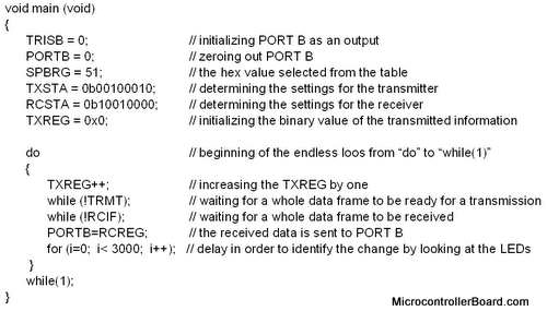
Writing a C language program to implement PIC micro serial communication
Now lets explore a simple program that shows how to transmit and receive information within the same PIC microcontroller :
The program will transmit information using USART which is located within the PIC, and will receive the information into the USART on the same board.
In addition, the program will turn on the appropriate LEDs based on the information received. The information starts from number 0 and grows each time by 1. As stated previously, the information is transmitted through pin RC6 and received through pin RC7. Thus, in order to use one EduPIC microcontroller board we need to short the pins RC6 and RC7. We will use a jumper to do so. You can see the connection in the picture below:
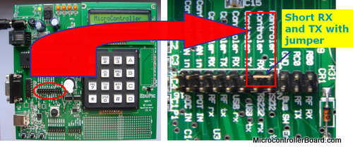
Example of the PIC micro serial communication program